Implementing and Operating Cisco Service Provider Network Core Technologies (SPCOR 350-501) — Free Practice Questions
10 free sample questions from a bank of 620, with the correct answers and explanations. No signup required — start practising right now.
- Configure back-to-back VRF-lite subinterfaces on R1 without MPLS BGP forwarding between ASBRs
- Configure MP-EBGP VPNv4 peering on R1 without MPLS forwarding on the inter-AS link
- Configure vrf definition on R1, bind the inter-AS interface, enable mpls bgp forwarding and mpls bgp signaling, then establish MP-EBGP VPNv4 peering to exchange VPNv4 prefixes with labels
- Configure GRE tunnels between ASBR loopbacks and run single-hop EBGP without label exchange
The short version
C — Use Option AB with VRF binding plus MPLS BGP forwarding and VPNv4 peering.
It keeps per-VRF control like Option A while exchanging labels like Option B.
Key concepts in this question
Inter-AS Option AB blends VRF awareness with labeled VPNv4 exchange.
The ASBR holds VRF interfaces and enables MPLS forwarding toward the peer so labeled VPN routes cross the boundary.
Why C is correct
Only C contains both Option AB prerequisites.
Binding the interface to the VRF plus mpls bgp forwarding with signaling and a VPNv4 EBGP session lets R1 forward labeled traffic across the inter-AS link, which is the banked C behavior.
Why the others are wrong
Each other option drops one Option AB half.
A omits label exchange so VPN reachability fails, B omits VRF-aware forwarding so per-VRF separation is lost, and D replaces the MPLS data plane with GRE which is not Option AB.
350-501 exam tip
Option AB equals VRF plus mpls bgp forwarding plus VPNv4.
Spot those three together for R1 ASBR tasks.
- Synchronize BGP and OSPF with AS 65517.
- Configure P1 as a route-reflector-client to PE1.
- Install route targets on alt PE routers under the VRF configuration for intranet services.
- Add the next-hop-self attribute under the BGP neighbor configuration for P1 on PE3.
The short version
B — Make P1 a route-reflector-client of PE1 so external routes get reflected to it. P1 has only one iBGP session (to PE1), and a plain iBGP speaker never re-advertises iBGP-learned routes, so prefixes the other PEs learned over eBGP die at PE1 and never reach P1.**
Key concepts in this question
- iBGP split horizon: routes learned from one iBGP peer are not advertised to another iBGP peer unless that peer is served as an RR client - PE1 therefore withholds every externally learned path from P1.
- Route reflector client:
neighbor P1 route-reflector-clienton PE1 turns PE1 into a reflector toward P1, licensing it to reflect all best paths (from non-clients and clients) to P1. - Session already up: connectivity is not the problem - the missing piece is the right to advertise those iBGP-learned paths onward.
Why B is correct
Cisco's route-reflector model states paths learned from non-clients are reflected to clients. Once P1 is a client of PE1, PE1 legally hands P1 every external path known anywhere in AS 65517, which is exactly what the stem asks for. No other option can deliver routes across the single PE1-P1 session.
Why the others are wrong
- A. BGP-IGP synchronization (the legacy
synchronizebehavior) only gates whether iBGP-learned routes are advertised before IGP verification; it never moves routes between iBGP peers and would suppress rather than deliver them. - C. Route targets decide which VPN routes import into which VRF; P1 is a core BGP speaker, not a VRF edge, so VRF route targets change nothing for it.
- D. next-hop-self on PE3 presumes a PE3-P1 neighbor, but the stem says only PE1-P1 was configured; next-hop-self also cannot overcome iBGP split horizon.
350-501 exam tip
iBGP splits horizon: an iBGP-learned route only reaches another iBGP neighbor if you full-mesh, confederate, or reflect - the client statement is the fix.
- TI-LFA uses PQ or P and Q nodes on the post-convergence path to compute the backup path.
- TI-LFA leverages the post-convergence path that carries data traffic after a failure.
- Unlike RLFA, TI-LFA works without the PQ node and provides double segment failure protection.
- Post-convergence, TI-LFA considers the next-hop neighbor to calculate the backup repair path.
- TI-LFA works with point of local repair when the PQ node supports only LDP capability.
The short version
A and B — TI-LFA precomputes a post-convergence repair path using P and Q nodes. It steers traffic along the loop-free post-convergence path immediately after failure.
Key concepts in this question
- TI-LFA (Topology-Independent Loop-Free Alternate): segment-routing fast reroute that works regardless of topology, unlike classic LFA coverage limits.
- P and Q nodes: P is reachable from the point of local repair without the failed resource; Q can reach the destination without it; PQ overlap defines the repair.
- Post-convergence path: the path traffic will use after IGP reconvergence, so repairing onto it avoids loops and microloops.
Why A and B are correct
TI-LFA uses PQ or P and Q nodes on the post-convergence path to compute the backup path (A) and leverages the post-convergence path that carries data traffic after a failure (B). The router precomputes a segment list that pushes repair traffic through those nodes, so on failure it forwards along the eventual converged route within milliseconds. Both statements describe that same standardized SR fast-reroute behavior.
Why the others are wrong
- C. TI-LFA still relies on P/Q computation, including extended P/Q space; claiming it works without PQ and adds double-failure protection overstates it.
- D. Considering only the post-convergence next-hop neighbor describes classic LFA thinking, not TI-LFA segment-list computation to P/Q.
- E. TI-LFA is a segment-routing mechanism, not an LDP-only point-of-local-repair behavior tied to LDP capability on the PQ node.
350-501 exam tip
Hook: TI equals post-convergence plus P/Q segments — if a choice says next-hop-only or LDP-only, eliminate it.
- Set loopback delay-frequency 50 and drop-threshold 0.2 on the PE routers.
- Implement mpls ldp tracing on the PE and P routers.
- Implement mpls oam policy oam on the PE routers.
- Implement mpls ip oam map-policy on the PE routers.
- Set loss-threshold 2 and delay-threshold 50 on the P routers.
The short version
C and D — MPLS OAM needs an OAM policy plus mapping it to traffic. The policy defines loss and delay thresholds and the map binds it for RFC 6374 and RFC 4379 measurement.
Key concepts in this question
- RFC 4379: LSP ping and traceroute for MPLS connectivity verification and fault isolation.
- RFC 6374: packet loss, delay, and throughput measurement for MPLS transport performance monitoring.
- IOS XR pattern: define an MPLS OAM policy with thresholds, then attach it with a map-policy command.
Why C and D are correct
Implementing mpls oam policy oam on the PE routers (C) creates the performance profile carrying the 2 percent loss and 0.05 second delay thresholds, and implementing mpls ip oam map-policy (D) binds that profile to the forwarding entries so probes are generated. With continuity check already at interval 1000, these two steps complete the standards-based loss and delay detection the Tier 1 provider requested.
Why the others are wrong
- A. Loopback delay-frequency and drop-threshold phrasing with mismatched units does not match the loss-threshold and delay-threshold policy model.
- B. MPLS LDP tracing is a troubleshooting capture aid, not the RFC 6374 performance-measurement policy requested.
- E. P routers are transit LSRs here; the requirement scopes the OAM policy to all PE devices, and the threshold values and placement are wrong.
350-501 exam tip
Remember define then apply: mpls oam policy first, map-policy second — thresholds alone without binding never take effect.
- Enable Cisco Express Forwarding on all routers in the backbone area.
- Implement mpls ldp sync on all routers in the segment.
- Update the routers in the segment to use RSVP-TE for label distribution.
- Implement mpls ldp autoconfig on all routers in the segment.
The short version
D — LDP autoconfig enables label exchange exactly on IGP interfaces. It ties LDP to the OSPF process so only IGP-enabled MPLS interfaces participate.
Key concepts in this question
- mpls ldp autoconfig: automatically enables LDP on interfaces already running the linked IGP without per-interface commands.
- IGP sync: LDP-IGP synchronization prevents traffic blackholes when LDP is not yet converged.
- RSVP-TE alternative: explicit tunnel-based label distribution, not automatic IGP-scoped LDP.
Why D is correct
Implementing mpls ldp autoconfig on all routers in the segment accomplishes the goal because the command enables LDP only on interfaces participating in the associated OSPF instance with TE extensions. New IGP interfaces inherit label distribution automatically while non-IGP interfaces stay excluded, which is exactly the requirement that label exchange be performed only on MPLS-enabled interfaces associated with the IGP instance.
Why the others are wrong
- A. Cisco Express Forwarding is a forwarding prerequisite for MPLS but does not scope label exchange to IGP interfaces.
- B. MPLS LDP sync coordinates IGP cost with LDP convergence to avoid blackholes; it does not auto-enable LDP on IGP interfaces.
- C. Moving to RSVP-TE replaces the label distribution protocol with signaled tunnels instead of constraining LDP to IGP interfaces.
350-501 exam tip
Autoconfig equals automatic plus IGP-scoped — use it when the question says only IGP interfaces should run LDP.
- Configure BFD demand mode with the command bfd-demand timer 150 interval 250 retransmit 5.
- Configure BFD echo mode with the command bfd interval 150 min_rx 200 multiplier 3.
- Configure the fast-hello feature for OSPF with the command ip ospf dead-interval minimal hello- multiplier 3.
- Configure BFD non-echo mode with the command echo interval 250 minimal 300 echo-multiplier2.
The short version
B — BFD echo mode gives 600 ms detection with low CPU. A 200 ms receive interval times multiplier 3 equals 600 ms, and echo offloads work to the forwarding plane.
Key concepts in this question
- BFD echo mode: echo packets loop through the neighbor forwarding path, reducing control-plane processing on the local router.
- Detection math: detection time is roughly the greater of transmit interval and receive interval multiplied by the multiplier.
- Versus OSPF fast hellos: sub-second OSPF hellos raise CPU load, the opposite of what overloaded R1 needs.
Why B is correct
Configuring BFD echo mode with bfd interval 150 min_rx 200 multiplier 3 meets the requirement because negotiated detection becomes max(150, 200) times 3, or 600 ms. Echo mode keeps periodic echo frames in the forwarding path so the overloaded R1 control plane does less per-packet work, limiting downtime after failure while lowering CPU compared with aggressive routing-protocol timers.
Why the others are wrong
- A. BFD demand mode with the cited timers does not yield the clean 600 ms echo-offload design and is not the standard fix for CPU overload.
- C. OSPF fast hellos with hello-multiplier 3 drive sub-second SPF churn on the CPU, worsening the overload on R1.
- D. The non-echo phrasing is malformed and lacks the echo offload benefit; it does not compute to the required 600 ms design.
350-501 exam tip
Compute max of interval and min_rx times multiplier, then pick echo when the stem complains about CPU.
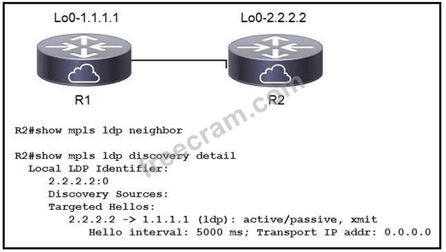
- R2 sees the wrong type of hellos from R1
- LDP needs to be enabled on the R2 physical interface
- LDP needs to be enabled on the R2 loopback interface
- R2 does not see any hellos from R1
The short version
B — LDP is missing on the R2 link interface. R2 shows an empty neighbor table and only targeted hellos, so no link adjacency to 1.1.1.1 can form.
Key concepts in this question
- LDP link hellos vs targeted hellos: directly connected peers need multicast link hellos; targeted hellos alone do not build a link adjacency.
- show mpls ldp discovery detail: lists the hello sources a router is actually using.
- mpls ip enablement: LDP must be enabled on the connected physical interface.
Why B is correct
R2# show mpls ldp neighbor returns nothing and the discovery detail shows only one source, Targeted Hellos 2.2.2.2 -> 1.1.1.1 (xmit), with no interface/link hello source. For two directly connected routers (Lo0 1.1.1.1 and 2.2.2.2) that proves LDP was never enabled on the R2 physical link, so R2 never forms the 1.1.1.1 neighbor.
Why the others are wrong
- A. No wrong-type hello is shown, only the absence of any received/link hello.
- C. The loopback/targeted hello is already transmitting (active/passive, xmit), so the loopback is not the missing piece for a directly connected peer.
- D. R2 seeing no hellos is the observed symptom, not the configuring factor; B is the fix the question asks for.
350-501 exam tip
Empty show mpls ldp neighbor plus only Targeted Hellos in discovery detail means mpls ip is missing on the link interface.
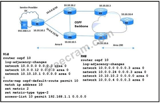
- Configure distribute-list route-map ospf-default-route out on router RM.
- Apply default-information originate route-map ospf-default-route on router RM.
- Apply default-information originate route-map ospf-default-route on router RL.
- Configure distribute-list route-map ospf-default-route out on router RL.
The short version
C — Originate the conditional default from RL. RL owns the tracked 192.168.1.1 interface and the route-map; RM does not.
Key concepts in this question
- default-information originate route-map: originates a default only while the route-map matches.
- Route-map tracking with ACL: match 192.168.1.1 controls origination; set metric 2 and metric-type type-2 shape the LSA.
- Placement matters: the command belongs on the router attached to the tracked prefix.
Why C is correct
The exhibit topology attaches the 192.168.1.1 application server to RL, and only the RL# config contains route-map ospf-default-route (match ip address 10 permitting 192.168.1.1, set metric 2, set metric-type type-2). RM# shows only network statements with no route-map. Applying default-information originate route-map ospf-default-route on RL makes OSPF area 0 originate the type-2-metric-2 default exactly while the server is up.
Why the others are wrong
- A. distribute-list filters routes; it does not originate a conditional default, and RM is the wrong router.
- B. Right command on the wrong router: RM has no tracked 192.168.1.1 interface or route-map, so the condition never fires there.
- D. Same defect as A: distribute-list on RL cannot originate the default LSA.
350-501 exam tip
Conditional default = default-information originate route-map on the router directly connected to the tracked prefix.
- It occasionally streams to multiple servers in the network.
- It uses the pull model to send requested data to a client when polled.
- It uses the push model to stream data to desired destinations.
- It is less secure because it uses community strings.
The short version
C — Model-driven telemetry pushes streaming data to collectors. It replaces slow polling with continuous subscription-based streaming.
Key concepts in this question
- Push versus pull: telemetry streams on change or cadence; SNMP traditionally polls on request.
- Model-driven: YANG models define the data schema encoded in GPB or JSON over gRPC or NETCONF.
- Advantage: fine-grained, high-frequency visibility for automation and assurance.
Why C is correct
Model-driven telemetry uses the push model to stream data to desired destinations. Routers publish subscribed sensor paths to one or more collectors at configured cadences or on change, giving near-real-time state without repeated management polling. That streaming push behavior is the defining feature tested against legacy pull-based monitoring.
Why the others are wrong
- A. Occasionally streaming to multiple servers understates the architecture; streaming is continuous and subscription-driven, not occasional.
- B. The pull model where the client polls and the device responds on demand describes SNMP GET, the opposite of telemetry push.
- D. Community strings belong to SNMPv2c insecurity; telemetry uses model-based transport with modern authentication and encryption.
350-501 exam tip
Contrast word: telemetry pushes, SNMP pulls — any pull-model choice on a telemetry question is wrong.
- It provides stateful session translation with the 2002::/16 prefix.
- It allows customers IPv6 traffic to be tunneled over IPv4 network infrastructure.
- It translates RFC 1918 IP addresses into public IP addresses.
- It provides native reachability between IPv4-only hosts and 6RD-enabled IPv6 hosts.
The short version
B — 6RD tunnels customer IPv6 across provider IPv4. It gives rapid IPv6 deployment without upgrading the entire IPv4 core.
Key concepts in this question
- 6RD (IPv6 Rapid Deployment): stateless encapsulation of IPv6 in IPv4 using provider-derived 6RD prefixes.
- Use case: ISP delivers IPv6 to homes over an existing IPv4 access and core network.
- Versus NAT and translation: 6RD is encapsulation, not address translation or stateful session mapping.
Why B is correct
One of the main functions of 6RD is allowing customer IPv6 traffic to be tunneled over IPv4 network infrastructure. The customer edge encapsulates IPv6 packets inside IPv4 toward the provider border relay, which decapsulates them to the IPv6 Internet, and return traffic follows the reverse stateless mapping. That tunneling function is exactly what answer B states.
Why the others are wrong
- A. Stateful session translation with 2002::/16 describes 6to4 mechanics, not stateless 6RD provider-prefix operation.
- C. Translating RFC 1918 addresses into public addresses describes NAT, not IPv6 transition.
- D. Native reachability between IPv4-only and IPv6 hosts implies translation such as NAT64; 6RD connects IPv6 endpoints across IPv4.
350-501 exam tip
Read 6RD as IPv6 over IPv4 tunnel — if the choice says NAT, stateful, or 2002 prefix, it is describing a different mechanism.
Want the full bank of 620 questions for Implementing and Operating Cisco Service Provider Network Core Technologies (SPCOR 350-501)? See all practice exams.