Designing Cisco Data Center Infrastructure — Free Practice Questions
10 free sample questions from a bank of 324, with the correct answers and explanations. No signup required — start practising right now.
The short version
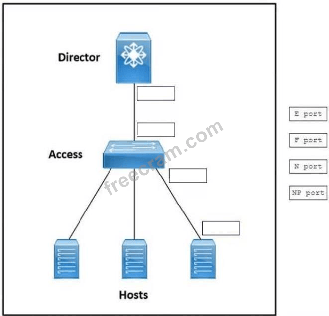
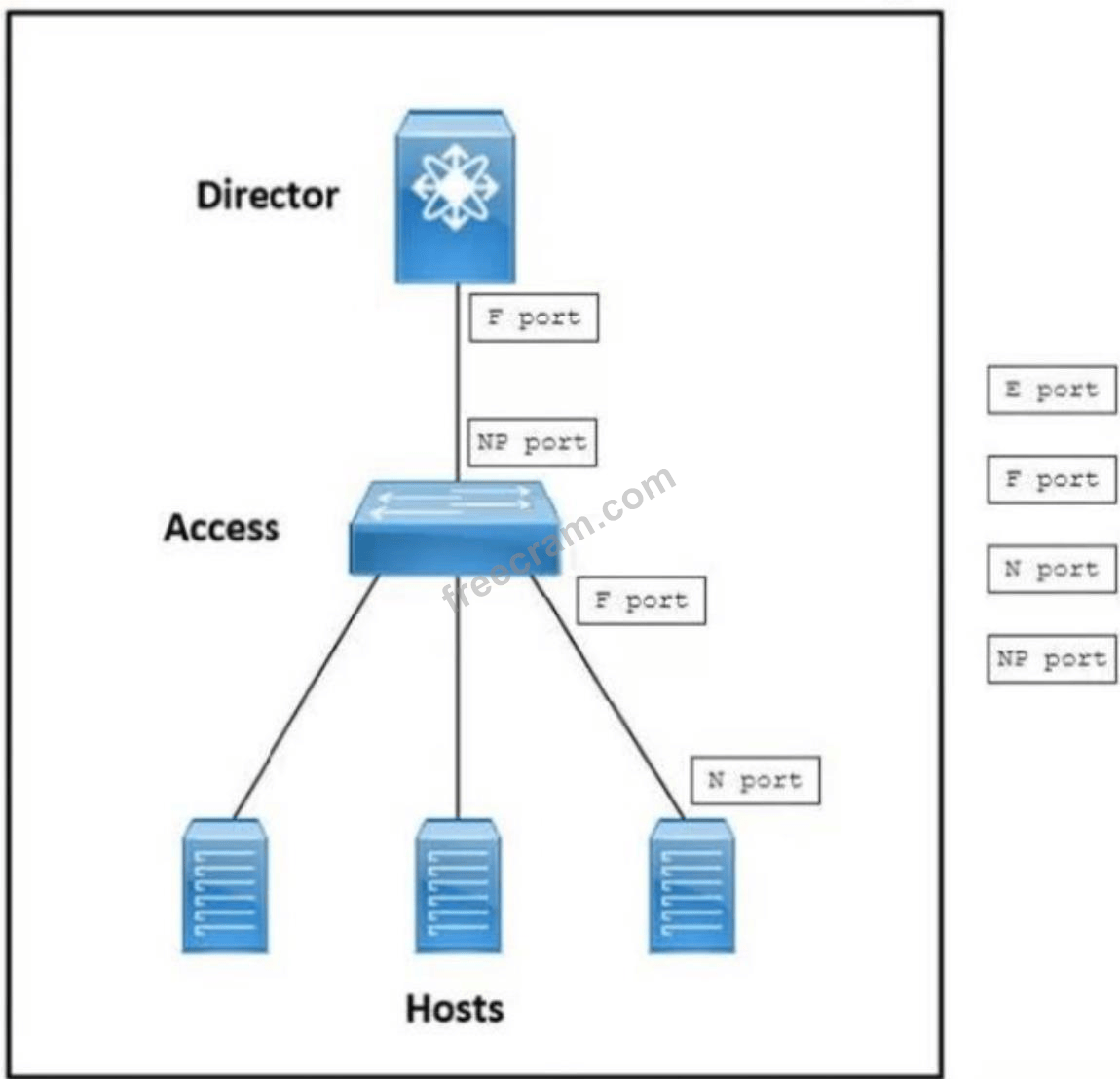
MATCH — upstream F, access uplink NP, access downlinks F, hosts N. NPV shares the upstream domain ID.
Key concepts in this question
- F Port: fabric port on the upstream director facing NPV switches and hosts
- NP Port: NPV uplink that proxies many downlinks over one uplink and uses the upstream domain ID
- N and F downlinks: host N ports connect to access-switch F ports for aggregation
Why this mapping is correct
NPV mode lets the access switch avoid its own domain ID by presenting downlink hosts through an NP uplink to an upstream F port, so the upstream director holds the single domain ID while multiple local F ports aggregate hosts whose HBAs are N ports; that matches the minimize-domain and aggregate-local-ports criteria exactly.
Why the others are wrong
- E or TE upstream: expansion ports trunk directors together and do not face an NPV access uplink.
- F uplink on access: a normal F uplink would consume its own domain ID instead of sharing upstream.
- NP to hosts: proxy uplinks never face end devices, only host F ports do.
- N on the switch: N ports live on hosts, switch sides are F or NP.
300-610 exam tip
Minimize domains plus shared domain means NPV: upstream F, access NP, downlink F, host N.
- - Set BGP AS to 65500- Configure RIP as an underlay IGP
- - Set BGP AS to 65501- Configure EIGRP as an underlay IGP
- - Set BGP AS to 65501- Configure RIP as an underlay IGP
- - Set BGP AS to 65500- Configure IGRP as an underlay IGP
The short version
B — DC2 joins with AS 65501 and EIGRP as its underlay. The distinct BGP AS separates the new fabric while EIGRP provides the loop-free underlay reachability the VXLAN-EVPN overlay rides on.
Key concepts in this question
- VXLAN-EVPN DCI: stretching endpoint reachability between data centers over an EVPN control plane.
- Underlay IGP: supplies VTEP loopback reachability beneath the overlay.
- BGP AS per fabric: distinguishes each data center in the DCI peering design.
Why B is correct
The design must propagate endpoint information end to end, which EVPN handles once each fabric has working VTEP reachability. EIGRP as the DC2 underlay IGP advertises those loopbacks and converges quickly, satisfying the transport requirement. Setting BGP AS 65501, distinct from the DC1 value, fits the multi-AS DCI pattern so each fabric keeps its own identity while exchanging EVPN routes. Together the two settings meet both criteria: endpoints propagate and configuration replicates cleanly.
Why the others are wrong
- A. Reusing AS 65500 removes the per-fabric AS separation the design calls for, and RIP scales poorly as a data-center underlay.
- C. AS 65501 is right, but RIP lacks the fast convergence and scale expected of a VXLAN underlay.
- D. IGRP is a long-obsolete protocol unsupported on modern platforms, so it can never be the designed underlay.
300-610 exam tip
For DCI designs, match each half: a distinct AS names the fabric, a real IGP feeds the VTEPs.
- end host mode
- N-Port lD virtualization
- static PIN grouping
- dynamic port pinning
- priority flow control
The short version
A and B — End host mode plus NPV saves domain IDs and pins traffic. NPV lets the fabric interconnects join without consuming a domain ID, while end host behavior enables the port-pinning control the design needs.
Key concepts in this question
- N-Port ID Virtualization (NPV): edge switches proxy host logins upstream so they use no local domain ID.
- End host mode: fabric interconnects present uplinks without running full SAN switching.
- Static PIN grouping: maps server traffic to a chosen set of uplink ports.
Why A and B are correct
Every native Fibre Channel switch normally consumes one of the limited domain IDs, and adding MDS switches plus UCS fabrics threatens to exhaust them. NPV avoids that by making the edge devices forward N-Port logins to the core instead of taking a domain ID, which is option B. End host mode on the fabric interconnects complements this by keeping the UCS side in host-forwarding behavior, the mode under which deterministic uplink pinning groups are administered, which is option A. Combined, they preserve domain IDs and deliver the required traffic mapping.
Why the others are wrong
- C. Static pinning alone organizes uplinks but consumes nothing and saves no domain IDs by itself.
- D. Dynamic pinning reacts to load rather than mapping traffic to a specific administrator-chosen port group.
- E. Priority flow control provides lossless Ethernet for FCoE; it manages congestion, not domain IDs or pinning.
300-610 exam tip
Domain-ID pressure always points at NPV; deterministic uplink mapping points at host mode plus pinning.
- 8-Gbps links use 64B/66B encoding, and 10-Gbps links use 8B/10B encoding.
- 8-Gbps links use 8B/10B encoding, and 10-Gbps links use 64B/66B encoding.
- 8-Gbps links and 10-Gbps links use 8B/10B encoding.
- 8-Gbps links and 10-Gbps links use 64B/66B encoding.
The short version
B — 8-Gbps links use 8B/10B while 10-Gbps links use 64B/66B. The slower links keep the older heavier-overhead code, and the faster links switch to the more efficient 64B/66B scheme.
Key concepts in this question
- 8B/10B encoding: maps each 8-bit byte to a 10-bit symbol, costing 25 percent overhead.
- 64B/66B encoding: maps 64 bits to 66-bit blocks, costing roughly 3 percent overhead.
- Encoding transition: Fibre Channel moved schemes as speeds outgrew the old overhead budget.
Why B is correct
At 8 Gbps the Fibre Channel line code is still 8B/10B, the same family used by 1, 2, and 4 Gbps links, which guarantees the DC balance and transitions receivers need. At 10 Gbps that 25 percent tax becomes unaffordable, so the standard switches to 64B/66B, whose 2-bit sync header per 64-bit payload wastes far less bandwidth. Option B states exactly that split, and it is the pairing every Fibre Channel speed table documents.
Why the others are wrong
- A. Reversing the schemes contradicts the standards: 64B/66B never ran at 8 Gbps and 8B/10B never scaled to 10 Gbps links.
- C. Claiming 8B/10B for both ignores the documented encoding change introduced for 10-Gbps operation.
- D. Claiming 64B/66B for both backports the newer code onto 8-Gbps links that standardized on 8B/10B.
300-610 exam tip
Read speed upward, overhead downward: 8 Gbps keeps 8B/10B, 10 Gbps graduates to 64B/66B.
- Implement unique VLANs for DEV and PROD.
- Configure independent routing protocols for DEV and PROD.
- Implement dedicated ACLs between DEV and PROD.
- Configure separate VRFs for DEV and PROD.
The short version
D — Separate VRFs isolate DEV and PROD end to end. Each team gets its own routing table, so overlapping addresses coexist and external access stays cleanly separated with fast provisioning.
Key concepts in this question
- VRF: an independent Layer 3 routing instance with its own table and interfaces.
- Route isolation: preventing one tenant prefixes from leaking into another.
- Overlapping IP support: identical subnets coexisting because each lives in a different table.
Why D is correct
The requirements combine isolation, overlapping addresses, and rapid deployment. Separate VRFs for DEV and PROD satisfy all three at once: each VRF holds a private routing table, so the same subnet can exist in both tenants without conflict, and remote external access terminates into the correct table with clean policy boundaries. Adding a new application is then a light operation inside its existing VRF, giving the transparent fast deployment the design demands.
Why the others are wrong
- A. Unique VLANs separate Layer 2 only; without routing isolation the same IP range still collides at Layer 3.
- B. Independent routing protocols add complexity yet share one table, so overlapping addresses remain unresolvable.
- C. ACLs filter permitted flows but do not create routing separation, leaving overlapping subnets broken.
300-610 exam tip
Overlapping tenant IPs on the exam always mean separate tables, and separate tables mean VRFs.
- VRF sandwich
- routed mode
- service graph
- VLAN stitching
The short version
A — A VRF sandwich forces traffic through the ASA. Placing the firewall between two VRFs on the fabric path makes host X to host Y traffic enter one VRF, cross the ASA, and exit the other for inspection.
Key concepts in this question
- VRF sandwich: firewall inserted between an inside and an outside VRF with no direct route between them.
- EVPN gateway fabric: the VXLAN-EVPN network acting as the interconnect between tenants.
- Forced service path: routing design that leaves the firewall as the only bridge.
Why A is correct
Deep packet inspection requires every packet between the hosts to physically transit the ASA rather than being routed directly across the fabric. The VRF sandwich achieves that by terminating host X in one VRF and host Y in another, with the ASA holding interfaces in both. Since no direct VRF-to-VRF route exists, return and forward traffic must cross the firewall, where DPI and security policy apply before re-entering the EVPN fabric toward the destination.
Why the others are wrong
- B. Routed mode describes the ASA forwarding personality, not the topology that diverts fabric traffic into it.
- C. A service graph automates service chaining in some controllers but is not the EVPN firewall-insertion construct asked for.
- D. VLAN stitching extends Layer 2 segments and would bridge traffic around inspection rather than through it.
300-610 exam tip
Need guaranteed transit through a firewall on an EVPN fabric: sandwich it between two VRFs.
- OTV
- vPC
- OSPF
- IS-IS
- VXLAN EVPN
The short version
A and E — OTV and VXLAN EVPN stretch Layer 2 over Layer 3. Both encapsulate Ethernet frames across the 10-Gb IP transport, giving applications LAN adjacency between sites.
Key concepts in this question
- LAN extension over IP: carrying data-link frames inside Layer 3 packets between sites.
- OTV: MAC-in-IP overlay purpose-built for data-center interconnect.
- VXLAN EVPN: MAC-in-UDP with a BGP control plane, also suited to DCI.
Why A and E are correct
Applications demand data-link adjacency while only Layer 3 transport exists, so the solution must be an overlay that tunnels Ethernet. OTV does exactly that by encapsulating Layer 2 frames in IP across the interconnect, which is option A. VXLAN EVPN likewise transports Ethernet segments over IP, adding a scalable BGP control plane for host reachability between sites, which is option E. Both satisfy the Layer 2 over Layer 3 requirement on the available 10-Gb transport.
Why the others are wrong
- B. vPC virtualizes two local switches into one logical node; it extends no VLAN across sites.
- C. OSPF routes IP prefixes and never carries raw Ethernet frames between data centers.
- D. IS-IS is another Layer 3 routing protocol and provides no data-link extension service.
300-610 exam tip
Hear Layer 2 needed but only Layer 3 available and reach for an overlay: OTV or VXLAN EVPN.
- Enable Windows 1Gb server full duplex
- Remove data encryption on the SSD
- Configure 802 1Qbb priority flow control
- Deploy a content delivery network
The short version
C — Enable 802.1Qbb priority flow control for lossless transport. PFC pauses only the storage traffic class during congestion, protecting FCoE throughput across the oversubscribed ISLs.
Key concepts in this question
- Oversubscription: 720 VMs sharing each ISL, so bursts routinely exceed link capacity.
- Priority flow control (802.1Qbb): per-class pause frames that create lossless Ethernet for FCoE.
- FCoE sensitivity: storage frames cannot tolerate the drops that normal Ethernet accepts.
Why C is correct
The math shows severe fan-in: hundreds of VMs per host, many hosts per chassis, and only two ISLs per fabric, so congestion on the fabric-interconnect uplinks is structural rather than occasional. FCoE mapped onto that Ethernet must not drop frames, and 802.1Qbb PFC delivers exactly that by pausing the FCoE priority class hop by hop while letting other classes continue. That lossless behavior removes the congestion-drop bottleneck behind the IOPS shortfall.
Why the others are wrong
- A. A 1-Gb server duplex setting is irrelevant to a fabric built on multi-gigabit fibre-channel-grade links.
- B. SSD encryption affects media latency, not the fabric congestion drops starving the hosts.
- D. A content delivery network caches web objects and has no bearing on block storage IOPS.
300-610 exam tip
FCoE plus congestion on the exam always resolves to lossless Ethernet via PFC.
- 9000 bytes
- 2000 bytes
- 2158 bytes
- 2240 bytes
The short version
C — FCoE needs a 2158-byte minimum MTU. That value fits the full Fibre Channel frame plus Ethernet and FCoE headers so encapsulated frames forward intact.
Key concepts in this question
- FCoE encapsulation: a native Fibre Channel frame carried inside Ethernet.
- 2158-byte budget: maximum FC frame plus FCoE, MAC, and VLAN headers.
- QoS MTU class: the no-drop policy must permit frames of at least that size.
Why C is correct
An FCoE frame stacks several headers: the encapsulated Fibre Channel payload up to 2112 bytes, plus FC headers, the FCoE shim, and Ethernet framing. The standardized floor that accommodates the worst-case stack is 2158 bytes, and Cisco QoS policy for the FCoE class must therefore allow at least that MTU. Anything smaller silently discards full-size storage frames, which matches the reported forwarding failure.
Why the others are wrong
- A. 9000-byte jumbo frames work but far exceed the minimum; the question asks for the floor, not a generous setting.
- B. 2000 bytes falls short of the encapsulated maximum, so large FCoE frames would still drop.
- D. 2240 bytes is a common descriptive buffer size, but the testable standardized minimum is 2158.
300-610 exam tip
Memorize 2158 as the FCoE floor: full FC frame plus encapsulation overhead.
- usNIC connection policies
- vNIC templates
- service profile templates
- network control policies
The short version
B — vNIC templates centralize VLAN tagging policy. One template defines tagged VLANs and interface properties, and every server bound to it inherits updates together.
Key concepts in this question
- vNIC template: a reusable UCS Manager policy defining fabric, VLANs, MTU, and QoS for virtual NICs.
- Centralized update: editing the template propagates to all bound service profiles at once.
- Post-deployment consistency: new VLANs roll to many blades without per-server edits.
Why B is correct
The customer needs tagged-VLAN management that is defined once and applied to many blade servers simultaneously, including after deployment. vNIC templates are purpose-built for that: the administrator edits VLAN membership and interface properties in the template, and UCS Manager pushes the change to every vNIC instantiated from it. That single-point control satisfies the central-update and multi-server requirements directly.
Why the others are wrong
- A. usNIC policies optimize low-latency HPC bypass traffic, not general VLAN tagging management.
- C. Service profile templates clone whole server identities, which is heavier than needed and not the VLAN-specific construct.
- D. Network control policies tune behaviors like CDP and uplink failover, not the VLAN membership list itself.
300-610 exam tip
Many servers, one VLAN change: think templates, and VLANs on NICs mean vNIC templates.
Want the full bank of 324 questions for Designing Cisco Data Center Infrastructure? See all practice exams.