Implementing Cisco Service Provider VPN Services — Free Practice Questions
10 free sample questions from a bank of 88, with the correct answers and explanations. No signup required — start practising right now.
- RT
- PW ID
- VC ID
- RD
The short version
D — The RD makes customer prefixes unique. Each PE prepends a Route Distinguisher to the 32-bit IPv4 prefix, producing a 96-bit VPNv4 prefix, so overlapping customer addresses stay distinct inside MP-BGP.
Key concepts in this question
- Route Distinguisher (RD): an 8-byte value prepended to an IPv4 prefix to create a unique VPNv4 route.
- VPNv4 prefix: 64-bit RD plus 32-bit IPv4 prefix, totaling 96 bits carried in MP-BGP.
- Route Target (RT): an extended community that controls VRF import and export policy, not uniqueness.
Why D is correct
In Layer 3 MPLS VPNs, different customers routinely use the same private IPv4 space. To keep these overlapping routes distinct in the provider backbone, the ingress PE attaches an RD to every customer prefix, forming a VPNv4 NLRI that is unique per VRF even when the IPv4 portion is identical. That is exactly the 32-bit to 96-bit transformation described in the stem, and it happens on the PE before the route is advertised to VPNv4 peers.
Why the others are wrong
- A. The RT selects which VRFs import or export a route; it is a policy tag, not the uniqueness prefix.
- B. The PW ID identifies a Layer 2 pseudowire endpoint, which is unrelated to IPv4 prefix uniqueness.
- C. The VC ID serves the same pseudowire-identification role as the PW ID and plays no part in L3VPN prefix encoding.
300-515 exam tip
Remember RD makes the route unique while RT decides where the route goes; uniqueness first, policy second.
- PE1(config)#12vpnPE1(config-12vpn)#xconnect group evpn-vpwsPE1(config-12vpn-xc)# p2p evpn1PE1(config-12vpn-xc-p2p)# interface Gig 1/0/1PE1(config-12vpn-xc-p2p)# neighbor evpn evi 100 target 12 source 10PE1(config-12vpn-xc-p2p)# commit
- PE1(config)#12vpnPE1(config-12vpn)#bridge group bg2PE1(config-12vpn-bg)# brige-domain bd2PE1(config-evpn)# interface Bundle-Ether10PE1(config-evpn-ac)# ethernet-segmentPE1(config-evpn-ac-es)# identifier type 0 00.01.00.ac.ce.55.00.0a.00PE1(config-evpn-ac-es)# commit
- PE1(config-evpn)# interface Bundle-Ether10PE1(config-evpn-ac)# ethernet-segmentPE1(config-evpn-ac-es)# identifier type 0 00.01.00.ac.ce.55.00.0a.00PE1(config-evpn-ac-es)# commit
- PE1(config)#12vpnPE1(config-12vpn)#bridge group bg2PE1(config-12vpn-bg)# brige-domain bd2PE1(config-12vpn-bg-bd)# interface Gig 1/0/1PE1(config-12vpn-bg-bd-ac)# routed interface BVI200
The short version
A — A VPWS cross-connect binds the attachment circuit to the EVPN instance. The l2vpn xconnect point-to-point block with a neighbor evpn statement ties interface Gig 1/0/1 to EVI 100, letting PE1 program the EAD route into its Layer 2 RIB.
Key concepts in this question
- EVPN-VPWS: a point-to-point EVPN service that emulates a wire using per-EVI Ethernet A-D routes for discovery.
- Per-EVI EAD route: signals that a PE has a local attachment circuit for a given EVI.
- xconnect p2p: the IOS XR construct binding a local attachment circuit to an EVPN neighbor and EVI.
Why A is correct
Single-homed EVPN-VPWS needs two halves: BGP EVPN signaling, already started, and a local cross-connect that maps the physical attachment circuit to the EVI. Option A supplies that half by creating a p2p xconnect, attaching interface Gig 1/0/1, and pointing it at EVI 100 with local and remote targets. Once that binding exists, the EAD route received from PE2 resolves to a forwarding entry and PE1 installs it in the Layer 2 RIB, completing the pseudowire.
Why the others are wrong
- B. Bridge groups, bridge domains, and Ethernet segments build multipoint ELAN or multihoming, not a single-homed point-to-point VPWS.
- C. An Ethernet segment identifier alone defines multihoming DF election state; without the xconnect it creates no VPWS binding.
- D. A bridge domain with a routed BVI builds an IRB gateway, which is a Layer 3 construct and the opposite of a transparent point-to-point wire.
300-515 exam tip
See VPWS on the exam and think point-to-point xconnect plus neighbor evpn; see bridge-domain and think multipoint ELAN instead.
- Enable control-word under the pw-class configuration on SPX.
- Enable preferred-path interface tunnel under the pw-class configuration on SPX.
- Configure neighbor 10.10.10.1 pw-id 1000 under a different xconnect group name.
- Configure SPX with the pw-class dynamic_mpls command under xconnect group MS-PW10 for SPX neighbors.
The short version
D — The switching node needs the dynamic pw-class on its MS-PW segments. Applying the pw-class under the xconnect group toward the SPX neighbors completes the multisegment pseudowire signaling so traffic passes between Site-X and Site-Y.
Key concepts in this question
- Multisegment pseudowire (MS-PW): a pseudowire stitched across a switching PE (S-PE) between two segments.
- pw-class: a reusable template carrying pseudowire parameters such as encapsulation and signaling mode.
- S-PE role: the middle node must switch, not terminate, the pseudowire toward each neighbor.
Why D is correct
IS-IS and LDP are already up, so the transport is healthy and the fault sits in the pseudowire layer. In an MS-PW design, each segment to the S-PE must reference a compatible pw-class so the switching node can stitch PW 1000 and PW 2000 together. Configuring the dynamic MPLS pw-class under the xconnect group for the SPX neighbors gives SPX the parameters it needs to signal both segments, which restores end-to-end connectivity between the sites.
Why the others are wrong
- A. The control word guards against frame reordering and payload misinterpretation; a missing control word does not by itself break MS-PW stitching here.
- B. A TE preferred path steers an already working pseudowire over a tunnel; it cannot fix segments that never signaled.
- C. Renaming the xconnect group is cosmetic because group names are locally significant and never affect PW signaling.
300-515 exam tip
When transport is up but an MS-PW is down, check the S-PE stitching config first: pw-class plus neighbor statements under the xconnect.
- CE1 must use OSPF to establish a neighbor relationship with PE1.
- PE1 labels the routes it learns from CE1 with the route-target 222:2 and shares them with its VPNv4 peers.
- PE1 labels the routes it learns from CE1 with the route-target 111:1 and shares them with its VPNv4 peers.
- The PE-CE routes between the devices are being exchanged by OSPF
- CE1 is supporting CSC.
The short version
C and D — PE-CE routing runs OSPF and exported routes carry RT 111:1. The exhibit shows OSPF exchanging routes between CE1 and PE1, with PE1 tagging those routes for its VPNv4 peers using the export target 111:1.
Key concepts in this question
- PE-CE OSPF: OSPF used as the edge routing protocol between customer and provider routers.
- Export route target: the RT attached to VPNv4 advertisements leaving the PE.
- Import versus export direction: export marks routes going out, import filters routes coming in.
Why C and D are correct
The configuration shows an OSPF adjacency between the CE and PE devices, so the PE-CE routes are plain OSPF exchanges, which is statement D. When PE1 redistributes those OSPF routes into MP-BGP, it stamps them with its configured export route target 111:1 so remote PEs know which VRFs should import them, which is statement C. Together the two statements describe the full loop: OSPF at the edge, labeled VPNv4 routes with RT 111:1 in the core.
Why the others are wrong
- A. CE1 peers with PE1, but the stem asks for conclusions supported by the shown config, and mandating OSPF as the only possibility overstates the evidence.
- B. RT 222:2 is the import-side value in this design, so it is not the tag PE1 attaches to routes it advertises outward.
- E. Nothing in the configuration indicates Carrier Supporting Carrier hierarchy, so CSC is unsupported.
300-515 exam tip
Read RT direction like mail: export is the stamp you put on, import is the mailbox you accept from.
- ethernet oam max-rate 8
- ethernet uni id 2004-20
- ethernet oam min-rate 8
- ethernet oam remote-loopback supported
The short version
D — PE2 needs remote loopback support for active link monitoring. Enabling remote-loopback lets the provider run loopback tests from PE2 toward CE1 over the E-OAM session, which is the monitoring capability the customer asked for.
Key concepts in this question
- Ethernet OAM (802.3ah): a slow-protocol link-monitoring toolkit between two directly connected Ethernet peers.
- Remote loopback: an OAM mode that loops test frames back at the far end for fault isolation.
- OAM peering: both ends negotiate capabilities before active tests can run.
Why D is correct
The customer wants extra monitoring on the CE1 to PE2 Ethernet link, and E-OAM is already up. Discovery alone only exchanges keepalives and event notifications; intrusive validation such as loopback testing requires the far-end capability to be enabled. Configuring remote-loopback support on PE2 completes the OAM capability set so the provider can loop traffic at CE1 on demand and verify the link without a site visit.
Why the others are wrong
- A. A max-rate value only throttles OAM frame pacing and adds no new monitoring function.
- B. A UNI identifier labels the attachment circuit for management correlation; it enables no test or measurement.
- C. A min-rate value only floors the OAM frame pacing and adds no new monitoring function.
300-515 exam tip
For E-OAM monitoring questions, loopback equals testing the wire, while rate knobs only tune protocol chatter.
- Configure ip ospf network non-broadcast under Gi0/0/1 on R2
- Configure router ospf 1 under the global configuration on R2
- Configure no passive-interface under Gi0/0/1 on R1
- Configure prefix-suppression under the global configuration on R1
The short version
B — OSPF was never started on R2, so no adjacency can form. Adding router ospf 1 in global configuration on R2 enables the process, after which Hellos can flow and the R1 to R2 neighbor relationship comes up.
Key concepts in this question
- OSPF adjacency: requires the OSPF process plus matching area, timers, MTU, and network type.
- router ospf process-id: the global command that creates the OSPF instance on a router.
- Log-driven triage: syslog messages distinguish a missing process from a parameter mismatch.
Why B is correct
Both routers share a subnet, area, and process ID on paper, yet R1 logs show no usable OSPF neighbor. The investigation points to R2 simply having no OSPF process running, so it never sends or answers Hellos on Gi0/0/1. Entering router ospf 1 under global configuration on R2 instantiates the process, and with interfaces then covered, Hellos begin, the two-way exchange completes, and the adjacency forms.
Why the others are wrong
- A. Changing the network type to non-broadcast adds DR and neighbor-statement complexity that a simple Ethernet link does not need.
- C. A passive interface suppresses Hellos, but the fault here is the absent process on R2, not a passive flag on R1.
- D. Prefix suppression only hides transit prefixes from advertisements; it has no effect on adjacency formation.
300-515 exam tip
No Hellos at all means check whether OSPF is even running before touching timers, MTUs, or network types.
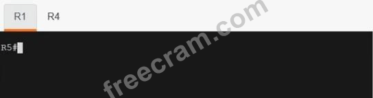


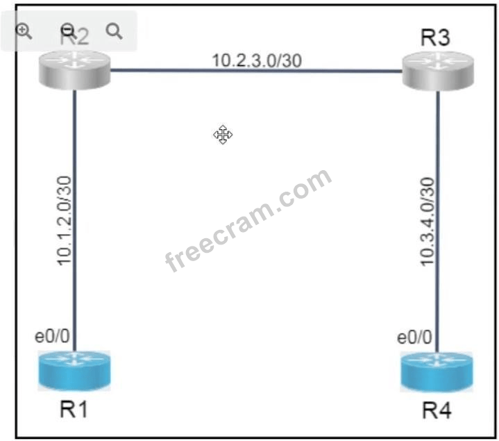


The short version
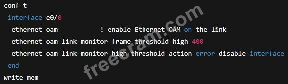
ORDER — enable E-OAM on E0/0, monitor error frames, set high threshold 400 with error-disable action, then save.
Key concepts in this question
- Ethernet OAM link monitoring: tracks error frames on the link
- High threshold 400: upper limit that triggers the violation action
- Error-disable action: blocks the interface when the threshold is exceeded
Why this order is correct
E-OAM must first be enabled on E0/0 before any link-monitor subcommands are accepted, then error-frame monitoring is selected with high threshold 400 and the error-disable action attached to it, and the configuration is saved to NVRAM last so the lab grading sees a persistent solution on both R1 and R4.
Why the others are wrong
- Enabling monitoring before E-OAM: link-monitor commands are rejected without ethernet oam on the interface.
- Setting action before threshold: there is no violation to act on until the 400-frame threshold is defined.
- Saving before configuring: saving early preserves the incomplete pre-configuration and loses the graded changes.
300-515 exam tip
E-OAM labs grade in sequence: enable oam, pick error frames, set 400, set error-disable, then write memory.
- MTU size
- pseudowire ID
- VLAN name
- control word usage
- Xconnect group name
- EFP subinterface number
The short version
A, B, and D — MTU, pseudowire ID, and control word must agree end to end. These three parameters shape the wire itself, so any mismatch breaks the EoMPLS pseudowire, while the remaining options are only local labels.
Key concepts in this question
- Pseudowire ID (VC ID): the identifier binding the two endpoints of one emulated wire.
- MTU agreement: both ends must fragment and reassemble identically or large frames drop.
- Control word: an optional shim whose presence or absence must match so payloads decode correctly.
Why A and B and D are correct
An EoMPLS pseudowire is a contract between exactly two attachment circuits. The VC ID selects which remote endpoint is the partner, the MTU guarantees both sides handle the same frame sizes, and the control-word setting determines the encapsulation format on the wire. If any of the three differs, the endpoints either signal different circuits or misinterpret each payload, so troubleshooting starts by matching all three.
Why the others are wrong
- C. A VLAN name is a local switch alias; only the numeric tag on the wire matters, never its text label.
- E. The xconnect group name organizes local configuration and is never signaled to the peer.
- F. The EFP subinterface number is locally significant numbering, so each side may number its own attachment circuit freely.
300-515 exam tip
Ask whether the parameter travels across the wire: IDs, MTU, and control word do, while names and numbers stay local.
- Disable spanning tree to allow loops to occur within the hub-and-spoke topology
- Disable Cisco Discovery Protocol to allow MPLS to share labels between the designated spokes
- Disable split horizon to allow multiple VCs per spoke
- Disable Cisco Discovery Protocol to allow for neighbor discovery
The short version
C — The hub must stop enforcing split horizon toward the multi-VC spoke. Disabling split horizon on R1 lets frames arriving on one VC of the new spoke leave on its other VCs, restoring hub-and-spoke forwarding.
Key concepts in this question
- H-VPLS: hierarchical VPLS with hub and spoke nodes to scale pseudowire meshes.
- Split horizon: the loop-prevention rule that blocks forwarding a frame back out the pseudowire it arrived on.
- Multiple VCs per spoke: several logical circuits from one spoke device into the same hub.
Why C is correct
VPLS uses split horizon instead of spanning tree to prevent loops, which normally forbids hub-to-spoke-to-spoke forwarding. In a strict hub-and-spoke design that rule is fine with one VC per spoke, but the new spoke brings several VCs whose traffic must hairpin through hub R1. Turning off split horizon on R1 relaxes that restriction exactly where the multi-VC spoke attaches, so frames can enter on one VC and exit on another while the rest of the loop protection stays intact.
Why the others are wrong
- A. Disabling spanning tree invites real loops and VPLS deliberately relies on split horizon rather than spanning tree.
- B. CDP has no role in MPLS label distribution, so toggling it cannot change pseudowire forwarding.
- D. CDP is a neighbor-discovery helper, not a forwarding control, and disabling it fixes no VPLS reachability problem.
300-515 exam tip
New spoke with several VCs breaks traffic flow: think split horizon blocking the hairpin at the hub.
- The CE1 and CE2 VRFs can exchange routes only between their respective VRFs on PE1 and PE2.
- All three routers must be running a distance-vector routing protocol.
- All three routers must be running MP-BGP.
- The CE1 and CE2 VRFs can access the default route provided by the Internet VRF.
- Only the CE2 VRF can access the default route provided by the Internet VRF.
The short version
C and E — MP-BGP runs everywhere and only the CE2 VRF learns the Internet default. All three routers speak MP-BGP for VPNv4, while the default from the Internet VRF on PE3 leaks solely into the CE2 VRF.
Key concepts in this question
- MP-BGP VPNv4: the core protocol distributing labeled customer routes between PEs.
- Internet VRF: a separate VRF on PE3 holding the Internet default route.
- Selective route leaking: importing a default into one customer VRF without exposing it to others.
Why C and E are correct
PE1 and PE2 already exchange VPNv4 routes, which requires MP-BGP sessions, and PE3 participates in the same VPNv4 control plane to source the Internet default, so all three routers must run MP-BGP, which is statement C. The leaking policy is asymmetric: the import target for the Internet default is configured only under the CE2 VRF, so CE1 keeps pure inter-site routing while CE2 alone gains Internet egress, which is statement E.
Why the others are wrong
- A. The VRFs do exchange routes with each other, but that statement alone ignores the selective Internet leaking that defines the design.
- B. MP-BGP is a path-vector protocol, so calling for a distance-vector protocol misstates the core routing type.
- D. A shared default to both VRFs contradicts the exhibit, where only CE2 is granted Internet access.
300-515 exam tip
One-sided Internet access in an MPLS VPN means an extranet-style selective import, not a global default.
Want the full bank of 88 questions for Implementing Cisco Service Provider VPN Services? See all practice exams.